Table of Contents
Cartridge-Designer
The Cartridge Designer is a powerful tool for designing and editing caliber specifications. This includes the definition of the cartridge and also that of the cartridge chamber, exactly as in the simple editing window of a caliber in the caliber database.
In the Cartridge Designer, however, you additionally have the real-time updating representation of a technical drawing of the specifications.
Note
 It depends from where you call this tool.
The behavior is displayed in the upper right corner of the window.
- If you select the Cartridge Designer from the toolbar or menu, you only edit the caliber specification stored in your currently active grtload file.
- If you call the Cartridge Designer from the Caliber Database, then you edit the respective entry from the caliber database.
Create New
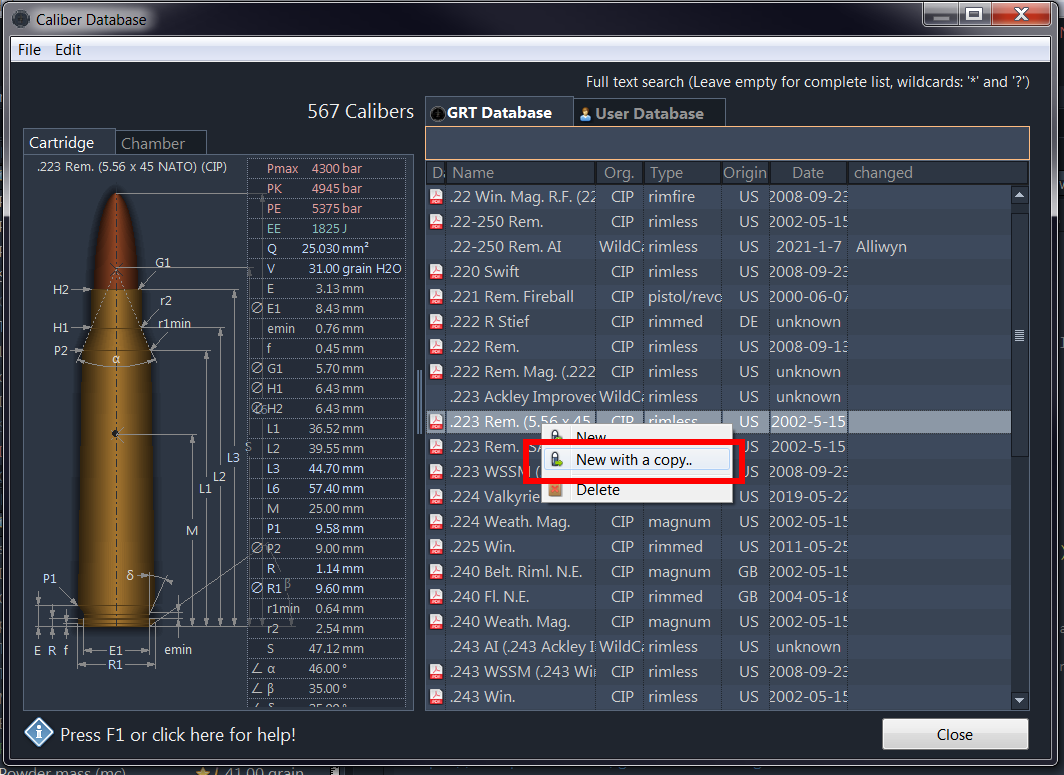
If you want to create a completely new Cartridge/Caliber specification, it is recommended, that due to the abundance of the necessary input parameters, you select a similar already existing specification as a basis and create a copy of it.
To do so, open the caliber database,
- select the desired entry, right-click and select “New with copy” to create a copy:
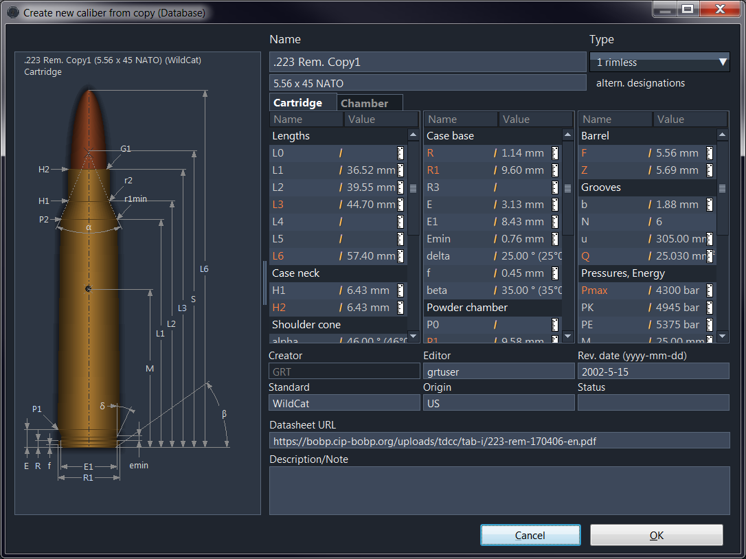
- The simple cartridge edit shows up:
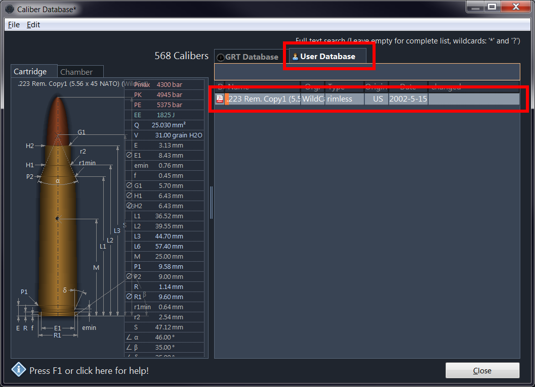
- Save it right away and it appears as user created file:
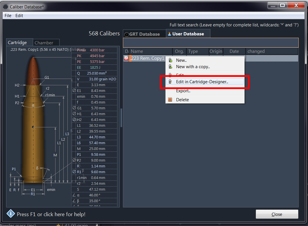
- select “Edit in Cartridge Designer” again by right-clicking on the newly created entry.:


Edit
Editing the individual Symbols/Dimensions is done in three tabs on the right side of the window.
The meaning of the individual symbols such as “L1” or “G1” can be found in the table at the bottom under “Meaning of the Symbols”.
- General - Edit the general data.
- Cartridge - Edit the cartridge/case.
- Chamber - Edit the cartridge chamber.

By editing the respective values of the symbols, you will change the dimensions of the drawing in real time.
If errors are detected, the corresponding fields are highlighted. Hold the mouse over an error line to get a description of the error at the top of the information bar.

You can click on a dimension directly in the drawing. The corresponding value in the list on the right list on the right and turned over automatically.

Meaning of the Symbols
Cartridge
| Lengths | |
|---|---|
| L1 | Length from case bottom to diameter P2 |
| L2 | Length from bottom of sleeve to diameter H1 of sleeve neck |
| L3 | Total length of the sleeve |
| L4 | Length from bottom of sleeve to diameter G2 |
| L5 | Length from bottom of sleeve to diameter F |
| L6 | Total length of cartridge |
| Case Head | |
| R | Rim thickness |
| R1 | Rim diameter |
| R3 | Belt diameter |
| E | Case Base Thickness |
| E1 | Diameter of milled groove |
| emin | Width of the groove |
| δ | Half angle of the milled groove (between E1 and P1) |
| f | Height of the phasing of the edge |
| β | Angle of the phasing of the edge |
| Powder Chamber | |
| P1 | Diameter at the end of the rim, before milling or at a distance E from the bottom of the sleeve |
| P2 | Diameter of sleeve at distance L1 |
| Shoulder | |
| α | Shoulder angle |
| S | Length to top of shoulder |
| r1min | Radius of transition at end of P2 |
| r2 | Radius of the transition between the shoulder and the neck of the sleeve |
| Case Neck | |
| H1 | Diameter at case neck at distance L2 |
| H2 | Diameter at case mouth at distance L3 |
| Bullet | |
| G1 | Bullet diameter at case mouth |
| G2 | Bullet diameter at distance L4 |
| F | Bullet diameter at distance L5 |
| Pressures (Energy) | |
| Pmax | Mean maximum allowable pressure |
| PK | Maximum allowable single statistical pressure = Pmax + 15% |
| PE | Mean impingement pressure = Pmax + 25% |
| EE | Minimum impingement energy (joules) |
| M | Position of the borehole in the case for pressure sensor position of proof barrels |
Chamber
| Barrel | |
|---|---|
| F | Lands diameter of the barrel |
| Z | Grooves diameter of the barrel |
| Lengths | |
| L1 | Length of chamber at diameter P2 |
| L2 | Length of chamber at diameter H1 |
| L3 | Length of chamber at diameter H2 |
| Breech | |
| R | Distance from breech face to the backward edge of barrel |
| R1 | Diameter of the breech |
| R2 | Depth of the breech |
| r | Junction radius at the chamber mouth |
| R3 | Diameter before the breech for belted cartridges |
| Powder Chamber | |
| E | Distance from butt plate to entrance of chamber |
| P1 | Diameter at entrance of cartridge chamber or at distance E |
| P2 | Diameter at beginning of transition cone at distance L1 |
| Junction Cone | |
| α | Angle of junction cone |
| S | Length to intersection of junction cone |
| r1max | Radius at end of diameter P2 |
| r2 | Transition radius at junction at collar |
| Collar | |
| H1 | Diameter at beginning of collar at distance L2 |
| H2 | Diameter at distance L3 |
| Transition | |
| G1 | Diameter at the beginning of the transition |
| G | Distance between H2 and F |
| α1 | Junction angle between H2 and G1 |
| h | Distance between H2 and G1 (angle: α1) |
| s | Distance between H2 and beginning of transition at diameter G1 |
| i | Half angle of transition slope |
| Grooves | |
| b | Width of grooves |
| N | Number of grooves |
| u | Twist length |
| Q | Effective barrel cross section |